Current Volt Amp Formula. Single phase va to amps calculation formula. An ammeter is a measuring instrument used to measure the current in a circuit.
Using Ohms Law in Basic Electrical and Electronics from axleaddict.com
An amp, short for ampere, is a unit of electrical current. P = v * i. Electrical current, measured in amps.
I = P / V.
Current (i) in amps is equal to the square root of power (p) in watts divided by the resistance (r) in ohms. Ampere (a) = volt (v) / ohm (ω) this formula is derived from ohms law. P = power (watts) v = voltage (volts) i = current (amps) looking back at our example of water flowing through a hose, we can now see how power is directly related to current and voltage using this equation.
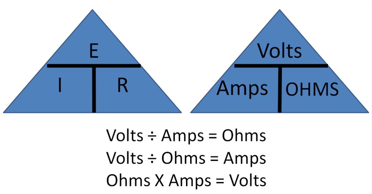
Lets Say, For Example, That We Have A Circuit With The Potential Of 1 Volt, A Current Of 1 Amp, And Resistance Of 1 Ohm.
If the current (i) and resistance (r) of any circuit is given we can mold the current formula to calculate the voltage, i.e., v = ir (volts). V = i x r. Hence the formula will be,
For Example, If You Have 6 Volts And 2 Ohms, Then The Resistance Is 3 Amps.
V = voltage in volts; R = resistance in ohms; As an example, if we consider 15% capacitor tolerance, 10% voltage tolerance and 20% additional current due to harmonics then the fundamental capacitor full load current has to be multiplied by 1.15*1.10*1.20=1.518.
I = Current In Amps;
Amps = watts / volts examples: The volt energy is measured in joules and so we need to. An ammeter is a measuring instrument used to measure the current in a circuit.
The Electric Current Is Measured In Amps.
An amp, short for ampere, is a unit of electrical current. What is the current in amps when the power consumption is 330 watts and the voltage supply is 110 volts? The amount of electricity passing through each bulb per second (the current) is the same, but the electric charges passing through one bulb have more energy than those passing through the other one.
Voltage Divider Schematic . See the voltage divider diagram. With respect to a common point or ground, usually 0v, or it could be across a dual supply, for example ±5v, or ±12v, etc. Voltage Divider Circuit Voltage divider, Circuit diagram from www.pinterest.com.au If the circuit variables are appropriately worked out, the levels of icq and vceq could be virtually completely independent of beta. The required output voltage (v out) can be obtained across the resistor r2. I want to calculate adc values.
Voltage Follower Circuit Using Op Amp . It is also commonly known as unity gain opamp amplifier or opamp buffer. These types of circuits provide better load regulation, than a simple zener diode and resistor alone. op amp Stepbystep explanation of how voltage follower from electronics.stackexchange.com A voltage follower circuit has a very high input impedance. Output voltage equivalent to the input voltage. There is no amplification of the voltage.
Voltage In Series Parallel Circuit . The relationship between these three parameters is governed by ohm's law, given as v = ir, where v is voltage, i is current, and r is resistance. 1.) the voltage across a component 2.) the current through a component 2.) the resistance of a component. Series Parallel Circuit Series Parallel Circuit Examples from electricalacademia.com Using voltage division, you get v x = v c ∗ 4 4 + 8 = v c 3. Now if there is any group of emfs that follow in series in such junctionless circuit then the total voltage or emf of the circuit will be the sum of the individual values, that. Above, we used values so that our formula for current yielded.


Comments
Post a Comment