Op Amp Voltage Controlled Gain. The attributes of an ideal op amp basic operation the basic operation of the op amp can be easily summarized. Gain = r f /r in.
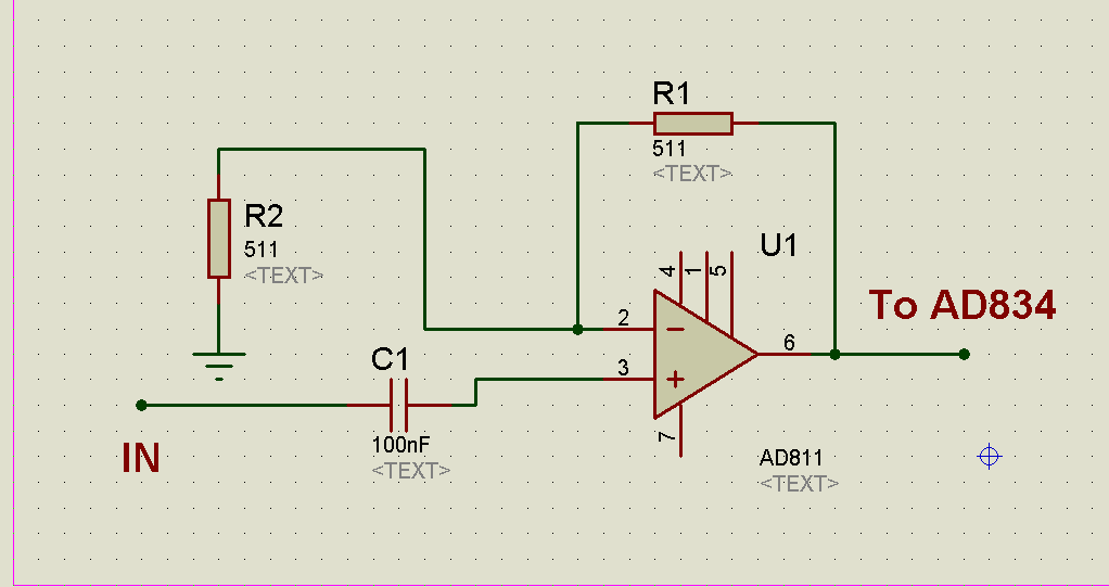
Why AD834+AD811 voltage controlled amplifier does not from electronics.stackexchange.com
Negative feedback is used to reduce the op amp's very high maximum gain to the required level. Current controlled current source d. A) to control the output voltage.
For The Inverting Amplifier The Multiplication Constant Is The Gain R2 − R1 And For The Non Inverting Amplifier The Multiplication Constant Is The Gain R2 1+ R1.
Negative feedback is used to reduce the op amp's very high maximum gain to the required level. •the virtual input short does not draw any current •for voltage purposes: So far we have explored the use of op amps to multiply a signal by a constant.
For Example If The Gain Is 5, Then The Output Voltage Will Be 5 Times Greater Than The Input Voltage.
But when i do this, the dc outputted in step 5 causes the signal to saturate at the op amps upper rail when low duties are used. •op amp is a voltage amplifier with extremely high gain (741, gain: However it is often useful to be able to vary the gain.
C) To Receive Zero Noise Output Voltage.
Op amps may also perform other mathematical operations ranging from addition and subtraction to integration, Increasing the control voltage above ground attenuates the signal path to greater than 80 db. The circuit is very simple and can be constructed with a minimum number of components.
As The Duty Increases And Inverted Copy Of The Duty Is Filtered Into An Analog Signal (Represented By V3) And Fed Through A Voltage Follower Connected To The Inverting Pin On The Amp With The Gain Stage.
60db range resulted by varying the diode bridge current over the range 1microamp to 5 milliamps. Gain = r f /r in. Digitally controlled vgas may be configured either for a few selectable decade.
40Db Was Given Over A.
The voltage gain is fully variable within these This is referred to as the voltage feedback model. An lm741 is a general purpose amplifier chip.
Voltage Divider Schematic . See the voltage divider diagram. With respect to a common point or ground, usually 0v, or it could be across a dual supply, for example ±5v, or ±12v, etc. Voltage Divider Circuit Voltage divider, Circuit diagram from www.pinterest.com.au If the circuit variables are appropriately worked out, the levels of icq and vceq could be virtually completely independent of beta. The required output voltage (v out) can be obtained across the resistor r2. I want to calculate adc values.
Voltage Follower Circuit Using Op Amp . It is also commonly known as unity gain opamp amplifier or opamp buffer. These types of circuits provide better load regulation, than a simple zener diode and resistor alone. op amp Stepbystep explanation of how voltage follower from electronics.stackexchange.com A voltage follower circuit has a very high input impedance. Output voltage equivalent to the input voltage. There is no amplification of the voltage.
Voltage In Series Parallel Circuit . The relationship between these three parameters is governed by ohm's law, given as v = ir, where v is voltage, i is current, and r is resistance. 1.) the voltage across a component 2.) the current through a component 2.) the resistance of a component. Series Parallel Circuit Series Parallel Circuit Examples from electricalacademia.com Using voltage division, you get v x = v c ∗ 4 4 + 8 = v c 3. Now if there is any group of emfs that follow in series in such junctionless circuit then the total voltage or emf of the circuit will be the sum of the individual values, that. Above, we used values so that our formula for current yielded.


Comments
Post a Comment