Working Voltage Of Electrolytic Capacitor. 400v working voltage 85 centigrade standard snap in type aluminum electrolytic capacitor In general, electrolytic capacitors are always polarized, i.e.
How Does A Capacitor Work? from www.electronicshub.org
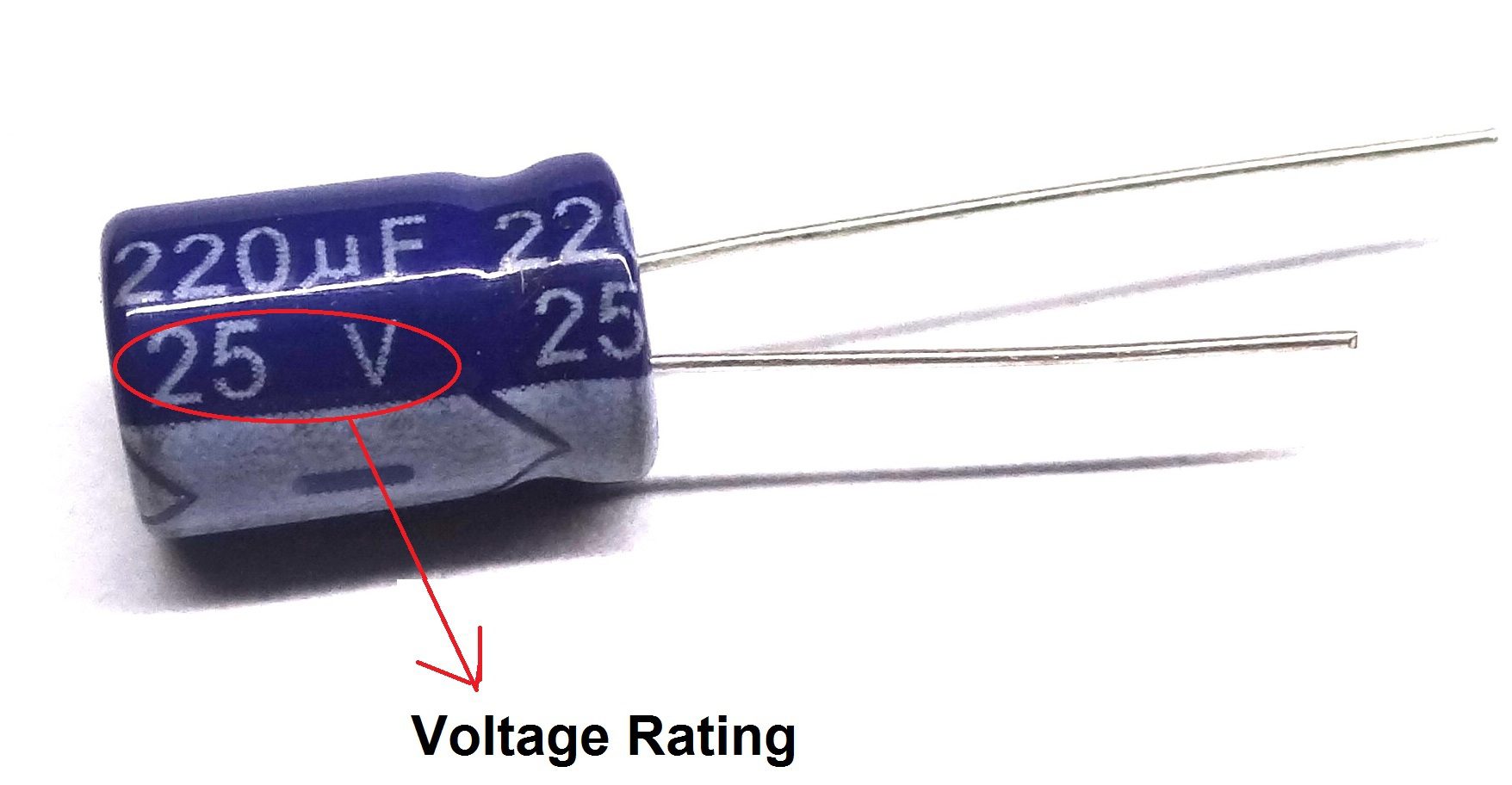
These have a typical capacitance between 1µf to 47mf and an operating voltage of up to a few hundred volts dc. The applied voltage to an electrolytic capacitor should be approximately equal to the voltage rating of the electrolytic. The value and working voltage is obvious.
Both Sides Of The Capacitor Are Moving Up And Down In Voltage At The Same Time, So The Voltage Across The Capacitor Is Close To 0 V, Even While The Voltage Of The Capacitor Relative To Ground Swings All Over The Place.
They are made with capacitance values from 0.1 μf to 2.7 f [24]. The applied voltage to an electrolytic capacitor should be approximately equal to the voltage rating of the electrolytic. The problem in your circuit that causes it to not work at less than 7v is that you are using a 12v relay as seen here.
Aluminum Electrolytic Capacitors (The Most Common Kind) Use Aluminum Oxide As The Dielectric.
For most practical purposes electrolytic capacitors can be considered to not have a minimum voltage rating. Voltage rating is the operating voltage of the capacitor and it is measured in volts. They can only be used for dc voltage.
Whereas Electrostatic Capacitors Are Specified For Test Voltages At 150…250 % Of The Rated Voltage, Specifications For Electrolytics State A Surge Voltage, Vs, Usually 110⋅⋅⋅115 % Of Vr.
Reversing the polarity of the capacitor or applying a voltage higher than the maximum rated working voltage of 1 to 1.5 volts can cause the dielectric to be destroyed and thus damage the capacitor. To reform the capacitor, the normal method is to apply the working voltage for the capacitor through a resistor of around 1.5 k ohms, or possibly less for lower voltage capacitors. The aluminum oxide is a thin layer formed by anodizing aluminum foil.
Each Capacitor Comes With A Working Voltage, And The Standard Values Are 100V, 250V, 400V, 1000V, 1600V, And Etch.
When an ac voltage is applied or the voltage source is incorrectly polarized, the insulating oxide layer is destroyed, the electrolyte evaporates and the capacitor bursts open. To test an electrolytic capacitor, here's what you need to do. Grab your digital multimeter and connect any capacitors to the meter.
400V Working Voltage 85 Centigrade Standard Snap In Type Aluminum Electrolytic Capacitor
It could be heard if expanded. The vibration of the prime one is a 50h z 60 h z electrical sound persuaded from the mains supply. 8.10c), depending on properties such as the working voltage, type of electrolyte, and applications [23].
Voltage Divider Schematic . See the voltage divider diagram. With respect to a common point or ground, usually 0v, or it could be across a dual supply, for example ±5v, or ±12v, etc. Voltage Divider Circuit Voltage divider, Circuit diagram from www.pinterest.com.au If the circuit variables are appropriately worked out, the levels of icq and vceq could be virtually completely independent of beta. The required output voltage (v out) can be obtained across the resistor r2. I want to calculate adc values.
Voltage Follower Circuit Using Op Amp . It is also commonly known as unity gain opamp amplifier or opamp buffer. These types of circuits provide better load regulation, than a simple zener diode and resistor alone. op amp Stepbystep explanation of how voltage follower from electronics.stackexchange.com A voltage follower circuit has a very high input impedance. Output voltage equivalent to the input voltage. There is no amplification of the voltage.
Voltage In Series Parallel Circuit . The relationship between these three parameters is governed by ohm's law, given as v = ir, where v is voltage, i is current, and r is resistance. 1.) the voltage across a component 2.) the current through a component 2.) the resistance of a component. Series Parallel Circuit Series Parallel Circuit Examples from electricalacademia.com Using voltage division, you get v x = v c ∗ 4 4 + 8 = v c 3. Now if there is any group of emfs that follow in series in such junctionless circuit then the total voltage or emf of the circuit will be the sum of the individual values, that. Above, we used values so that our formula for current yielded.


Comments
Post a Comment